MOSFET Package and Thermal Checklist for Replacement Buyers
Check package drawings, mounting, PCB heat paths and measurement conditions before sourcing power MOSFET replacements.
Published 3 November 2026 · Mosvanta editorial · Updated 4 November 2026
Check the exact package drawing and pin assignment before comparing thermal figures. Identify how heat leaves the device in your assembly and read the conditions behind each thermal resistance value. PCB copper, cooling and mounting affect performance. For pulled parts, inspect the mounting-related surfaces and record the condition of the offered lot.
Decision checklist
| Check | Evidence to request | Reason to pause approval |
|---|---|---|
| Mechanical fit | Drawing, lead geometry and mounting arrangement | Package name used instead of dimensions |
| Thermal path | PCB, mounting surface and cooling assumptions | Test-board result applied to any assembly |
| Used condition | Lead, tab and package photographs | Visible inspection treated as hidden-integrity proof |
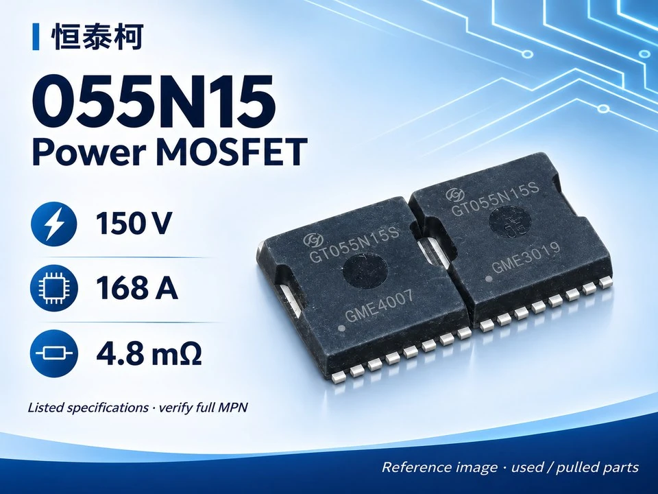
A package name is only the starting point
Before buying a replacement MOSFET, compare the exact package drawing and pin assignment. Check dimensions, lead geometry, mounting arrangement and exposed metal surfaces. Similar-looking devices can require different footprints or mounting details. Use the manufacturer documentation for the complete part number.
Identify the heat path in the actual assembly
Heat can leave a device through its package, mounting surface and PCB. The relative importance of those paths depends on the package and assembly. A thermal number measured on one test board does not automatically describe your product. Review the PCB copper, cooling arrangement and operating environment with the engineer responsible for the design.
Compare thermal figures under matching conditions
Distinguish junction-to-case or mounting-base data from junction-to-ambient data. Read the measurement conditions and boundary assumptions. Do not use an advertised current rating as a standalone operating-current recommendation. The real design must satisfy its electrical and thermal limits together.
Inspect the mounting-related condition of used parts
Request close photographs of leads, tabs, mounting holes and package surfaces as applicable. Record bent or trimmed leads, solder residue, cracks and visible damage. Photos help establish visible condition but do not measure hidden integrity. Ask what was inspected and keep the results linked to the lot offered.
Make sample approval meaningful
Compare an identified sample with the intended assembly and document the engineering review. Review mounting materials and process requirements using the applicable device guidance. Keep any differences from the approved device visible in the purchase record. If the package or source changes, decide whether a fresh assembly and thermal assessment is required.
Source and next steps
Nexperia: thermal boundary conditions for MOSFET packages. General selection guidance; confirm exact values in the manufacturer datasheet.
Browse our MOSFET directory and prepare your request with the RFQ checklist. Product workbook entries are sourcing references, not independent performance certification.
What should stop an order?
Pause approval when the full part identity, agreed condition or evidence needed for your decision is unresolved. Ask the supplier to clarify the specific gap. Keep the response with the order record so that a later buyer can see what was actually approved.